Wednesday, September 30, 2026

End of Summer report on the Breeze semi recumbent bicycle


The Breeze this summer (click on pictures to enlarge)
It's nine years ago that I gave up my car because I had become too disappointed with how I got around.  This was very unexpected, because in my family I've been the gearhead who had the Porsches, Mercedes, Fiat Abarth, Austin Healeys, the BMW, Yamaha, and Honda motorcycles.  I've put 356C engines in a VW bug and a Karmann Ghia, had a souped up 1957 VW bus, and took part in SCCA Formula Vee.  Because I think it's such a neat car, I still have the broken Porsche 912 I blew up.  It took a lot for me to become disillusioned with cars.  But I think our transportation system is now mostly expensive bandaids over systemic problems.   There's now twice as many drivers who travel twice as many miles each year compared to when I was younger, and we knew cars had serious problems back then.  One third of people can't drive, and cities need less traffic not more.  Unless you're a fossil fuel company looking to misinform people for another year of record profits, it's just plain poor planning to expect everyone to drive.  I decided I'd rather be working on better solutions.

Taking measurements before drawing
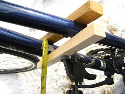
I started this bike by building a seat, and then using a mockup of 2x4's and plywood to position the seat and pedals so that I could measure the clearances to my legs for the bodywork.  I positioned slats of wood so that my legs would just clear them while pedaling, while also experimenting with different seat, pedal, and handlebar positions.  The RANS Stratus parked next to the mockup is for comparisons because I have experience riding it.


I've used NanoCAD free but have switched over to QCAD
Then I transferred the measurements to a 2D CAD drawing to adjust everything to fit together.  In this closeup the sloping red line in front of the handlebars is the maximum height of my legs, and the red circle above the pedals shows the top of my shoe clearance below the front bin.  The clearance between my knees and the brake levers was the most difficult part.  The finished bike has 1 1/8" clearance to my shins and knees.  Although there is + 3 inches of seat adjustment and the handlebars are adjustable, this bike is generally a tailored fit for my size.

All of my bikes have been meant to make my everyday errands safer and more comfortable on a rural road network designed for cars (i.e. with unwalkable distances between destinations).  When it became apparent that the F(when all you have is a car everything looks like a speedway)HWA  and my state Departments of  Transportation (Vermont and New Hampshire) were very capable of widening interstates I-89 and I-95 within a few years but not able to provide good bicycle infrastructure for me in my lifetime, it meant I had to start building the transportation system I wanted from my end.  The Breeze was designed to be the equivalent of a car.  I started off the design by using measurements from the RANS Stratus semi recumbent bike that I enjoy, combined with measurements from the similar Easy Racer semi recumbents.  But the best all around cars I've owned, (1989, 1990, 1992 Saab 900 hatchbacks), had the same seat height and foot placement, so I also copied the Saab steering wheel and seat angles too - this bike is like driving in my Saabs.  While the Breeze is a semi recumbent and uses different muscles to pedal and balance than an upright bike, (I steer by tilting my head slightly, and I would not be able to climb local hills without the electric assist), I have truly zoned out in comfort on this bike.

A tall roof would affect balance  Photo credit: Unternehmer TUM GmbH
Sometimes bike designers have used full bodywork for weather protection, such as velomobiles and this bike from the Technische Universität München "Mobilität neu erleben mit dem Reisefahrrad Läufer" (New mobility experience with a rotor pedal bicycle) project.  I'm concerned about the top heavy weight of a tall roof and the stability in side winds, and though the Lit enclosed motorcycle uses gyroscopes to deal with this problem, I wanted to keep it simple.

Minimal frontal area   Photo credit: Porsche Newsroom
I decided instead to take a Le Mans Prototype (LMP) approach with minimal bodywork covering each component, and used a cargo bin in front of the rider as the primary aerodynamic/weather protection  device.

The front bin is the main aerodynamic device, however in the future I could also add a Vee shaped panel under the bin in front of the pedals similar to the engine shroud on Ninja style motorcycles.  The aero is designed for front to back flow while minimizing the side area.  The bin is made from 3/16" Luan plywood (sometimes called Philippine mahogany).  When I was a carpenter we used this as underlayment to smooth out lumpy floors, and I had saved some pieces with quilted grain which I used for this bin.  Although the bin floor is level, the bottom of the sides slope down to the front (parallel to the solar panel) to provide more leg weather protection.  The sides were kerfed to bend the rounded front and it's coated with a spar urethane varnish.
 
The bin floor and the solar panel have a small arch to prevent drumming.  I left the back of the bin open for access to snacks, gloves, glasses, etc. while riding.  The solar controller is on the right, with a 48VDC to 5V USB-C converter in behind it, the dashcam display in the bin opening, and the BBSHD display on the handlebars.

Between the smaller semi recumbent frontal area and the rounded bin, this bike is fast.  I made 40 test runs coasting down moderate local hills to compare it to my mountain bike (which has the same tires).  Rolling at a commuter speed of 10 mph at the top of each hill, the average speeds (coasting, in mph) at the bottom were:

1. paved 700 feet @ 3.3 degrees:  MTB 24.7 / Breeze 28.1,  (difference 3.4 mph)
2. gravel 75' @ 8.4° then 200' @ 5.2°:  MTB 25.1 / Breeze 28.4,  (difference 3.3)
3. paved 680' @ 3.8°:  MTB 25.7 / Breeze 29.9, (difference 4.2)
4. paved 1250' @ 2.8°:  MTB 21.4 / Breeze 25.9, (difference 4.5)
5. paved 790' @ 4.8° then 600' @ 3.7°:  MTB 30.3 / Breeze 39.1 (difference 8.8)

Overall the average Breeze coasting speed was 4.8 mph faster than the MTB, but it shows up at higher speeds.  The aerodynamics made hardly any difference at regular commuting speeds around 12 mph, but the fastest test hill was 8.8 average (9.6 peak) mph faster.  This hill was a bit scary, because while my coasting MTB would peak around 30 mph and stay at 30, the Breeze was already at 34 at the bottom of the first slope and continued increasing to 40 mph through the second slope before I called it off - there is third steeper downslope after that and I wasn't willing to bring a new unsorted bike up to 50.  These aren't my steepest hills though and once the testing is done I expect 50 mph coasting will be crossed, this is a good situation for adding regenerative braking (however this will require custom hardware).

A typical chart of speed versus chances of death
Graph credit: ITE Community of Transportation Professionals
At 40 mph enough air pressure builds up at the front of the bin that the solar panel lifts up an inch even though it is angled down to the front, and I started to think about a side gust of wind or pavement rut knocking me over.

Perhaps this bike is unnecessarily fast.  In the big picture I measured the approximate time it took me to ride the coasting test route and the Breeze's extra coasting speed wasn't that significant.  I won't give an analysis here because I stopped at least 12 times to write notes over the 12 mile route, but the Breeze test routes took maybe 52 minutes versus maybe 55 minutes for the mountain bike.  It's mainly because the higher top coasting speed lasted for a shorter time than the slower climbs up the hills, often one gear slower for the Breeze because it's 50 pounds heavier.  (This reminds me of the power versus speed conundrum, where traveling twice as fast uses power squared but this lasts for half as long.)  Also the 4 stop signs took the same amount of time for each bike.  While bicycle commuter routes should be planned to be safe at coasting speeds higher than the legal ebike 20 mph limit, there are other significant factors road engineers should optimize when conscientiously minimizing bicycle commuter travel times the same as they would for car drivers.

On the other hand the extra speed helps me control passing cars better.  Although 80% of people rate themselves as above average drivers, I've noticed that car drivers mindlessly expect to pass me on any of my bikes, even when I've experimented with riding 28 mph in a 25 mph zone - they still pass.  To increase my safety I try to control where a car passes me by speeding up or slowing down ahead of time to make them pass in a location or gap in traffic where I prefer them to pass.  This will change with the Breeze because it is harder for a car to pass a fast bicycle than a slow one, and most likely I will see an increase in stupid driving maneuvers.  (There are times when I wish I could press a button and change my bike into a tractor pulling a full manure spreader.)

The solar panel is a 100 watt ERA Flex Pro 100MD that I cut 3/8" off each edge to remove the grommets and reduce the size, and then painted the edges black.  The solar controller is an SX Electronics that I was delighted to find because the Genasun GV Boost on my other bikes were far too expensive.  However I have not put a meter on the solar output yet and can't report how well this setup works.  The panel is mounted with a flexible silicon/vinyl hinge and extremely light aluminum clip and elastic cord latches that are attached with 3M VHB double face tape.  (The improvements of this setup are hard for me to believe compared to the solar I put on the bakfiets 12 years ago.)  There is a tremendous amount of air coming off this panel above 20 mph, and I'm thinking of attaching a 1950's style small sports car polycarbonate windshield to the back edge of the solar panel and increasing the panel arch to divert more of the air flow to the sides.  The dashcam display is visible between the handlebar display and the panel.

This mandatory Class 1 sticker is because while about 40% of people actually love bikes and another 40% are fine with them and don't think twice, the remaining 20% are loud and not afraid to display their misconceptions.  Since I can coast twice as fast as the motor will power the bike, this sticker serves a narrow demographic.

I used a BBSHD motor because the BBS02 on my other cargo bikes was sometimes a little too warm after a trip (I could just barely touch it).  This is the same line of thought as the oversized heavy duty diesel engines used in tractor trailers.  While I've programmed this motor to meet legal requirements and stop assisting at 20 mph, this bike has no problem coasting up to 40 mph.  It takes only a slight incline to reach coasting speeds of 25 to 29 mph and then it just keeps rolling. Since the bike coasts much faster than rolling under motor power, I think the arguments about ebike top speeds should be about the situation not the motorized speed.   Bikes are quiet and if you pass a walking person from behind, even at 8 mph, they will be startled and say you were going too fast.  This is not an excuse for the illegal high powered moto-ebikes that are actually mopeds, but looking beyond the need to ride appropriately for the situation, I've been thinking instead about how fast I actually wish to ride because I enjoy bicycling for many other reasons.

left - panel retracted, right - panel in canopy position
There is a pivot in behind the seat for a solar canopy.  I haven't built this assembly yet so you'll have to imagine a 60 watt solar panel in place of the horizontal white board in these photos.  The pivot is just a square taper bottom bracket and I'll extend the crank arms on each side to form the support linkage for the panel canopy.   This would function as a roof during rain and then retract for better aerodynamics when dry.  A drop down clear polycarbonate windshield to steady the canopy would attach between the canopy front edge and the back edge of the solar panel using Velcro.

I installed a dashcam because I'm trying to convince my Regional Planners to improve Route 5 (the main Connecticut River valley road through Vermont and New Hampshire) as a bicycle corridor.  I wanted to take documentary pictures of the dangerous spots to bring to legislators.  I started off with a GoPro camera on the handlebars because that is what everyone uses, but found that it could only film for 12 to 18 minutes before shutting down from overheating.  The picture quality is superb with stabilization, horizon leveling, and GIS, but it's really best for shots lasting only a minute or two not hours.  I then installed a car dash cam which also had GIS, but because it's not waterproof I attached everything with Velcro to be able to take it in during rain and then promptly lost the rear camera when it shook enough to fall off.  I now have a bolted on weatherproof motorcycle dashcam, but it doesn't have GIS and I can also say that VGA resolution (640x480) is not good enough.  This camera breaks the filming session into 5 minute long files which is convenient, but 32 GB stores only 7 of them.  While I'm figuring out a better setup I'm using Google Maps Street View and QGIS instead.

The front dashcam camera mounts under the edge of the solar panel, and the rear camera is under the tail light.  I've used about 20 different ebike headlights over the years and find this Sate-Lite C7 Plus the best for my rural use with the most focused beam, good side lobes, and a strong anti glare cutoff.

This bike is pretty good but I would like to build a second improved version with the lessons learned.  I should explain a few of the more complicated improvements in separate posts, but here's a brief list of some ideas:
- It should be lighter - it weighs 49 pounds on the front wheel and 54 on the back (includes everything except the rider)
-move handlebar support tube forward an inch for more clearance getting on and off
-move swingarm pivot 3/4" forward (due to 44T to 36T chainring evolution)
-dual chain loops are great but motor speed could be faster and pedals slower
-the front chain loop could be 2 speed not 3, with a chainstay style derailleur
-I used a 71 degree head angle to reduce front end drop/flop and it's nimble on pavement but too quick on loose gravel
-steering linkage versus cables, and steering ratio (a long story)
-make rear rack 3 inches shorter and increase to 6 inches wide
-axial generator for regen in place of rear brake disc
-16 inch seat width, and move one inch of the side tubing from top to bottom
-test comparison of SX Electronics vs Genasun mobile solar controllers
- inverted Tee battery support with a larger wiring box+frame reinforcement
-the dual battery combiner won't accept regen
-wiring solar into one battery sometimes turns on displays under flickering sun
-front suspension
-APT 750C motor display has problems
-BBS02+single battery versus BBSHD+dual battery???
-motor programming is different than for my MTBs
-motorcycle style roll on/off kickstand, not expanding leg style
-solar canopy
-parking pawl on front wheel for short term locking
-seat heater and heated hand grips
-aero windshield
-4th try at a dashcam

I live where most people hike, bike, kayak, and enjoy the outdoors in the Green Mountains, the Connecticut River valley, and the White Mountains, and it's ironic that I've built a bike to simulate a car.  This bias in US transportation can be traced as far back as the 1920s, (such as Herbert Hoover's policies as US Secretary of Commerce), and I'd think that the drawbacks with unilateral car based travel for everyone have become so obvious that our infrastructure would be different by now.  It isn't.  This bike helps me fit into a car based system, but most people don't have this choice.  I'm going to build another bike with lessons learned, but I'm hoping the road designers and builders also build more inclusive roads. Whether they admit it or not, serving only cars is a conservative political choice shaping how all people move, and now that much of road funding is from general tax funds not the gas tax, it's unprofessional.  If you can build a multilevel highway interchange, you can build a bike lane.  If you can provide free parking, you can provide a bike lane.  When I ride in a safe space I like to say thank you to the road builders who understood this.


Thursday, November 27, 2025

The Breeze recumbent cargo bike frame is rolling!


The Breeze is now a rolling chassis.  Although it still needs a front trunk with a solar panel lid, a retractable solar canopy, a deflector in front of the pedals, and oversize rear panniers built, I'm finally able to ride it around (before snow!)  I started building this single track semi recumbent electric cargo bike during the Covid quarantine while I was ruminating on the role of bikes (and walking) in a car culture.  As a result there are several unusual details which I can write more about this winter, but for now I thought I should put up a few photos.  (Click on the pictures to enlarge them.)

Single track recumbents are steered more by your hips than the handlebars so some people may have a difficult time riding one, (those with back or balance problems), however I've used a RANS Stratus for a few years and greatly enjoy it, so I wanted to build a heavy duty version that can haul groceries better.  I didn't want to have to push this bike home while I'm commissioning it, so I've ridden it for 2.5 miles just around the yard so far.  It's OK on grass, even with the motor shut off.  It does feel a little unusual when I get on it and it sinks 1/2 inch to sag position, but there hasn't been any pogoing or wallowing.  I have a steep, long, gravel driveway and it tracks very comfortably down to 2 or 3 mph going uphill or down so I think most of the dimensions are correct, but of course now that I've built it I can see a dozen little details that I'd do different next time.  The one odd behavior I don't fully understand is when I try to U-turn within a lane's width (10 to 12 feet wide), I end up leaning way over (40 degrees) at which point the front wheel turns sideways, the bike comes to a stop, and I do a slow roll onto the side.  (I need to U-turn to the left to spare the derailleurs!)  I eventually learned how to U-turn my bakfiets within one lane so this geometry/ergonometric speculation is mostly in case I build another frame.

Technically this is a Class 1 ebike: it has a Bafang BBSHD motor which I've programmed down to 720 watts (15 amps at 48 volts) and 20 mph to make it legal for both Vermont and New Hampshire, and I didn't install the throttle.  It has 26"x1.5" tires for mud season, with 8 speeds for the motor plus 3 more for the rider (two chain loops as 1x3x8).  There are 2 batteries totaling 1.68 kWh for longer trips, (plus I'd like to try heated grips or seat cushion).

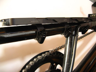
The horizontal display mimics a car dashboard.  On the right is a standard Shimano SL-R440 8 speed shifter for the rear cassette.  I ended up using an upside down Shimano Deore 6 speed thumb shifter (hidden under the Bafang keypad on the left) for the motor mounted high/mid/low range cassette because the cable pull was the best match after I had to shim the sprockets to avoid chain rub.  The front trunk bin will mount on the horizontal tube using the welded on m8 nuts, and the handlebars should be just below the height of the flexible solar panel lid to give wind protection for my hands.  Although the handlebars are minimum width, the bell fit ergonomically in front of the display.  The curvature of the handlebars are a natural angle for this riding position, (Mike Burrows' Soup Dragon used a similar arc).  To reduce the handlebar interference with my legs there is a slight step up ratio (1.2:1) on the steering, but I need to rack up some mileage to see if this is a good idea or not.

I included a bottom bracket at the front of the rear rack as a pivot for the retractable solar panel canopy, and when the top is down a 60 watt panel should extend just beyond the rack to the end of the bike.  The head and tail lights required a solid state relay circuit because the BBSHD supply was not powerful enough, and I tested 11 ebike headlights to find one with good focus and cutoff like a car headlight - I'll try to post a blog with this data during the winter.

Even though the bikes I build are just for getting myself around, I couldn't resist painting my Scarlet Runner Bikes logo on the head tube and down tube to try to trick people into thinking this one is from a factory.  (Also I think the Scarlet red looks good on the Chicory blue.)  This winter I'll try to post about more design considerations (there's a lot to say about the suspension besides the headlights), but our legislature will be coming into session soon and I expect to spend some time advocating for better bike/ped infrastructure on Route 5.  (Thank you all you other advocates who are helping bring about a better human scale transportation system.)  Now to get in some test miles before the salt, dirty slush, and ice will make it difficult to finish up the bodywork.

Monday, September 8, 2025

The Breeze frame is painted, plus a little bike advocacy

The Breeze single track semi recumbent frame (click to enlarge)

Last month I finally finished welding all of the small mounting tabs on The Breeze frame and sprayed a coat of chicory blue paint on it.  All of the small hardware still needs to fitted and this will take a while because I've done some unusual things (like cutting a freehub in half and mounting it on the motor's square taper crank).  But it's kind of neat and the rear suspension is actually supple, so I thought I'd post a picture of it.

I started this frame during Covid, but ended up building it as a side project because bike advocacy work became more important.  I've been using my ebikes as serious transportation since 2010, and next month will be 8 years without a car.  I live 5.5 miles away from the center of my small town in a rural area, and roads have become important.

In his book "One Less Car", Zach Furness quotes Sara Stout as saying:
"At first bicycling is utilitarian, it's just how you choose to get around... but it becomes political really quickly because it's hard to get around.  There are difficulties at every turn, and there seem to be injustices at every turn."

Being a builder geek I was a bit slower to understand this problem than Sara, but after 5 to  6 years it occurred to me that our roads have some major design flaws for anyone outside of a car, and this was scaring many people away from riding everyday like I was doing.  I started locally by asking my town manager and select board to include bicycles and pedestrians in their plans, but it grew and now I'm part of several transportation organizations.  One of my biggest supporters has been my state Sierra Club chapter - they have a Clean Transportation for All (bike/pedestrian/transit/EV) campaign.  I've been given the opportunity to testify 3 times before my state legislature for better support for bicycling and walking, and now I'm advocating to make US Route 5 in Vermont (along the Connecticut river from Massachusetts to Canada) safer for bicyclists and pedestrians.  Besides local river valley biking, this route would fill in a missing north-south Rail Trail system gap between the Farmington Canal trail starting on Long Island Sound up to La Route Verte in Quebec.  You don't have to be as involved or technical as I've gotten, it's just important to show up because otherwise all that the transportation people hear are car drivers loudly demanding pothole repair and more parking.  I actually think pretty highly of the people I've met at my state DOT, but all these agencies need to hear there is a demand for bike/ped facilities to justify taking time and money away from cars.  Now that I've stepped back from cars I can better see the insanity of all the externalized costs and effects of our car based transportation system and feel like speaking up, but please show up even if you just watch, or sign a petition, quieter voices need to be heard too.

Back before Covid I realized that our transportation system was not going to change quickly enough for me.  Since I had to travel 11 miles one way for groceries, 6 miles another way for the Post Office or bank, or 16 miles another direction for errands, I needed a bike that was more car-like to fit in with the existing road network.  My bike had to compensate for 1950's planning that expected people to drive a fast car everywhere. 

There were 3 main design inspirations for this frame.  To start, a semi recumbent would be similar to a car and I have a RANS Stratus that I've liked.  However the Stratus twists too much when there is a large load of groceries on the rear rack, and the fiberglass seat without any rear suspension can be a rough ride.   I used pedal drop and reach dimensions from it combined with dimensions from an EZ Racer and a mock up.  Second, my last few cars were Saab 900's (the early version), and aside from inaccessible service components they had a design philosophy with their planes I liked.  I used the 18 inch seat height, the 60 degree steering wheel angle (in line with shoulder joints) and other packaging and ergonometric details.  Third, I've loved Porsche cars since grade school in the 1960s, so the Breeze was getting a mid motor.

To these basic parameters, I added 26 inch wheels (for dirt roads) with rear suspension, a front storage compartment with a solar panel cover to keep rain off of me, dual batteries for longer distance, and a retractable solar canopy with a drop down windshield.  It took quite a bit of drawing to get it all to fit together, but we were quarantined for Covid anyhow.  The bodywork is going to take some time, but I expect to be riding the bare frame this fall to find out if it is going to work or not.  As I put it together I'll post more pictures of the details.

Sunday, December 10, 2023

A flat work table for making cargo bike frames

Cargo bike frames don't fit very well on a standard bike frame building jig.  I've gotten around this by placing a sheet of plywood on a flat section of the floor and lofting the plan on to it.  This has been very solid and square, but my knees and back are starting to complain.  When I decided last spring that it was time to start building the two wheel recumbent frame I've been dreaming about, it was also time to build a worktable.


A machinist's metal worktable is usually a carefully machined cast iron or steel surface that weighs a ton or two, is damaged after the first few projects, is not portable, cost more than my budget, and doesn't play well in small spaces.  The next most stable bench would be a woodworker's 2" to 3" thick laminated hardwood top, which is still too substantial for my space.  My projects weigh only 20 pounds and this bench is for layout and fitting, not hammering, so the surface mainly needs to be flat and long.  This rules out most welding tables.  Last summer a neighbor put out a flat panel hollow core door free for the taking at the end of his driveway and I thought it would be perfect, but after washing it and putting it in the sun to dry I found that hollow core doors will sag and warp.  This left only plywood or medium density fiberboard (MDF) for a top.  Because MDF sometimes snaps in two when bent, I used plywood.  However I used 3/4" CDX and then spent hours gluing veneer and adding wood filler to make a smooth surface.  If I build another table I'll use a better grade. or even a hardwood plywood.

Dimensions
The top is 30" wide by 80" long.  Measuring the bikes I have, the tallest frame was just under 24", and the longest frame (not counting the forks) was 82".  I wanted to be able to move the table outside while set up and my exterior door has a clear opening of 33" wide, however any clamps around the edge would take up 1-3/8" on each side, so I rounded to 30" wide for easy math while measuring from either side.
Similarly I decided to use 80" long for easy math, although it could leave a few inches of a frame hanging over the edge.  This isn't a big concern because the frame jig can extend past the table.  I took some time to make the edges of the top very straight, square, and parallel to use for references during measuring (less than 1/64" deviation over the length).

The table is 34" tall.  While standing with my arms bent at the elbow so that my forearms were horizontal, I drooped my hand as though I was working on tubing, and measured the height of my fingertips.  (This placed the tabletop 3-1/2" below the bottom of my elbows.)  This turned out to be very comfortable, close enough to see well when coping notches but not so high that I had to splay my arms.out sideways when reaching across the table.

The top and frame
Plywood warps, and the top is secured to a strong frame with thumb knobs so that it can easily be adjusted flat with shims stuck between the top and the frame.  
A 2x4 frame.assembled with 6" screws and construction adhesive provides a rigid base for the plywood top.  Allowing for a 4" wide lip around the top to fit my F clamps, the frame is 22"w x 72"l.

Attaching the Top to the Frame  Eight blocks glued and screwed to the underside of the table fit into the corners of the frame to locate the top.  After painting everything with a one part epoxy paint, the sides of the blocks were covered with clear plastic shipping tape to prevent the blocks from sticking to the frame.  I originally thought I'd use fixtures that clamp through the table (similar to a machinist's metal table), and drilled three rows of holes.  However the jig makes this unnecessary, and only the center row is needed for anchoring the jig to the table.

Underside view of securing the top to the frame.  The blocks fit snug into the corners of the frame, and a thumb knob is used to pull the top tight.  I used 5mm thick corner braces designed for metal shelving to resist bending as the knobs were tightened, but the brace tolerances were terrible.  After cutting the corner weld apart and bending the braces square on a press, I drilled 1/4" holes in the sides and mounted them on the frame with a 1/8" gap to the blocks.  In this picture I've drilled a hole in the brace and the block that fits a 5/16" stair handrail bolt, (which has a wood thread on one end and machine screw thread on the other), and have tightened double nuts on the bolts and screwed them into the blocks.  In the center are a couple of thumb knobs, and in the can are handrail bolts that I've shortened to fit the knobs.

A Typical Frame Jig  Since the bike frames were less than 24" tall, a thin sheet of plywood can be ripped in half lengthwise and used as the base for building a jig.  The table has a row of 1/4" holes down the center and the jig base is fastened to the table with several carriage bolts to keep it from moving around.  Then the design is easily drawn onto this base with tape measures and tee squares using the accurate edges of the table for reference.  Next shim blocks are glued onto the base drawing to hold the frame parts in alignment - the widest part of this bike frame is the 5.5" rear rack, and all blocks were cut to hold parts at a 2.75" centerline.  I used a tablesaw to cut the blocks out of scrap 2x4, but a miter box should work as well.  Tabs were glued to the sides of the blocks to help position the parts, but as the frame was assembled the warpage from welding gradually accumulated to create a tight fit, and it might be better to screw these tabs on so that they can be repositioned.  I ended up using a sheetrock knife or chisel on a couple of them.  I used 1/4" thick plywood for the base which flexed enough to let me finish building the frame, but this picture taken towards the end of building shows three F clamps holding everything down flat to the table while a pair of sticks clamped to the seat mounts are used to line them up parallel with the table.

A multitude of holes is needed in the center row to allow several positions for jig bolts to leave spaces for squares or other marking devices on the drawing while fitting up the frame.  A dial gauge holder with a sheet metal strip can be held against a part such as a bottom bracket, and then the bracket removed and a long tube slipped under the strip to be marked for length.  I've found that bottom brackets vary in outside diameters, so I cut discs that fit inside the brackets that were glued on the blocks to locate the brackets.

Legs  Folding shelf brackets attach the legs to the frame, which reduces the rocking to about 1/4 that of standard folding table leg hinges.  The disadvantages are the legs fold an inch wider and there is almost no sideways racking resistance. but this table only needs to fold enough to be out of the way against a wall, and the legs are paired together by a sturdy cross brace that prevents sideways movement.  Since the legs butt directly against the frame side rails and a cross member, the table is quite strong.

End Results  After shimming, the top is very flat with no light showing through underneath a 72" straight edge.  The table was also adjusted flat across the width using a yardstick, and a pair of winding sticks were used at several locations to remove twist.  There are a few small dips but the jig helps to smooth them out, and this is more than flat enough for a bike frame.

For comparison, a jig for a regular bike frame would be about half as large.

The rear rack clamp set up was much easier than propping up the rails any other way.  A 4" wide board between the two rails kept them parallel, and a 90 degree angle plate (made of plywood) lined up on the drawing kept the rails both straight and perpendicular.  The tail end of the rack does extend off the edge of the table by 4", but there are enough jig props that it doesn't matter.


Another example using the plywood 90 degree angle plates is holding side rails vertical on a recumbent seat frame.  I've made a couple of these seat frames on a smaller surface with a tight fit and the rail ends have turned out slightly misaligned.  For the next seat I'll draw out a rectangle on plywood fastened to the table and glue on stop blocks in the corners to hold the rails square and parallel, and then use the angle plates to keep them vertical while I tack weld the cross supports.  Note: only tack welds are done on the table, and then the assemblies are taken over to my metal cutting cabinet where I can rotate the assembly during welding to minimize distortion.   I also use scraps of sheet metal under the tack welds to reduce weld spatter burning the jig.

If you would like to build a recumbent seat, a basic pattern with instructions can be found at Recycled Recumbents:
I've found that his pattern has about 3/4" too much lumbar support and is about 3" too tall for me, and I've combined his pattern with angles from a couple other seats to suit me.

The Breeze  The first project on this table was the frame for The Breeze, my two wheel recumbent cargo bike, built this fall and nicely straight with well aligned angles.  It still needs battery and solar panel mounts, and a steering linkage, but I have to install components and check the clearances on them first.  I've spent well over a year sketching this frame in Nanocad Free (https://nanocad.com/products/nanocad-free/) to be sure everything fit, and this winter the project will finally be building the rear swingarm, the part that I started the design with 2 years ago.  I've been spending a lot of time on advocacy for better bike/ped infrastructure, (such as a bike corridor along Route 5 from Massachusetts to Canada), but hopefully next summer you'll see some blog posts about the complete bike.

All in all the table has been very comfortable, reducing bending when test fitting tubes and going back and forth to a workbench, and is a vast improvement in jig holding and accuracy.  If I did need to use it for rougher work I could cover it with a plywood or sheet metal layer and still have the flatness.  As it is though it saves a lot of measuring, straight edge work, and string layout, and is straight for 80". Very nice!

Sunday, August 21, 2022

Calibrating a Spoke Tension Gauge and looking at the results

My spoke tension gauge has helped me get a more even tension for the spokes on each side of a wheel than I was able to achieve by plucking the spokes.  But I've never trusted the tension conversion tables provided by companies, even if their gauges look the same as mine.
A slightly different pivot bushing or spring and the kg tables aren't correct
(click on all images to enlarge)
I have the Deckas version, which was affordable, smooth (after a few drops of oil), and quick.  It's worked well.  But last winter in my quest for knowledge, I bought 3 full suspension frames, (because no one I know would let me touch their bikes), and took them apart to study the pivots.

A Stumpjumper, Altitude, and VP-Free that now need wheels 
With 6 wheels to build, it would be really handy if I could use my tension gauge to measure absolute tension instead of just the relative tension between spokes.  I found Dan Burkhart's video about his calibration jig for a spoke tension gauge:
Dan Burkhart's DIY spoke tension meter calibrating device
video on YouTube is a good read

Spoke tension is often recommended to be between 70 to 140 kgf (154 to 308 pounds), so I got a 300 kg digital scale (200 kg would do) that used standard AAA batteries and appeared to have decent accuracy (claiming the OIML R76 standard) and 0.1 kg resolution.  It would be possible to hang the scale and simply wire a spoke to the hook, and then wire a 5 gallon bucket to the bottom of the spoke to fill with metal bits for weight and skip building a test fixture.  However I decided that repeating the test once in a while (for example after dropping my spoke gauge), as well as calibrating different spokes, would both be much easier if I had a calibration fixture.

My spoke tension calibration fixture is easy to build
Looking through my scrap metal pile, I found a nice 2" x 2" x 28" long x 0.094" wall square tube for a backbone for my jig that looked rigid enough to give reliable results. It came off an old exercise machine. People put them out by the road hoping someone will take it after they've realized it's just taking up space, and when I see one that has been sitting outside for a month or two I sometimes pick it up if it might have useful parts. This tube for leg lift weights was the right length and even had 1/2" holes already drilled in one end for slipping a bolt through, it seemed to be waiting to find a new and more useful life.

Mounting the scale to the tube
After sliding a long 1/2" bolt through the tube holes, the spoke had to be 1.25" above the frame for my Deckas spoke gauge to fit, so I used a short piece of automotive rubber coolant hose pushed over the bolt as a spacer.  Another short piece of hose between the scale and the nut provides some give that lets the scale move for alignment so that the load cell inside it doesn't get twisted and give false readings.

Connecting the scale to a spoke
Since the scale was built with a hole for a hook, a stirrup with a plate for the nipple was a natural connector choice.  I kept the U bolt narrow to reduce the spring, but made it long so that I could get my fingers and a nipple inside.  It's 1/4" rod, with a 5/16" thick cross plate that can be changed out for different spoke ends.

Connecting the J bend to the threaded rod
A simple plate as thick as a hub flange with a 2.6mm hole is all that's needed to connect the J bend.  Because I wanted the plate to be changeable to plates for other spoke styles, it's held with a removable 3/16" pin in a slot that I cut into a threaded rod coupling nut with a 1/8" grinder blade.  One problem I can see with Dan's fixture is rotation of the eye hooks as he adjusts the tension.  The red plate in this picture that is sandwiched between the coupling nut and a lock nut is an anti twist shoe that slides along the main tube to prevent this rotation. It also helps hold the threaded rod in position while installing spokes.

The anchor for holding the threaded rod and an alternative mount
I had a short piece of 2" wide x 1/4" flat bar, and after drilling a hole for the threaded rod 1.25" up from the main tube, I welded it on the end.  However if you want to make this fixture without welding, a substitute could be bolting on a short cross piece of ell angle iron.  I used 7/16" threaded rod because I had a short piece, but 5/16" or 3/8" would probably work considering that a spoke is around 2.0mm.  A smaller diameter rod would have a finer pitch which would make adjusting tension more precise, I found 1/8 turn of the nut gave about 10 kg change.  However I put all the test results into a spreadsheet and derived an equation, so it wasn't necessary to aim for exact tension numbers or gauge readings.  Either method should produce a good conversion table, but I'll say that my digital scale took well over 5 seconds to settle and making many small adjustments to reach a particular number could be tedious.

The first round of testing- how well does it work?
I clamped the jig to a table top with woodworking clamps while making tests, but with it's square main tube it could also be held in a vise.  It turned out to be easy to adjust with one wrench, and had excellent repeatability regardless of tightening or loosening direction, suggesting that these components are very rigid with little spring, and the scale is of reasonable quality.  As time goes on though I expect to compare the digital scale against others to be sure it isn't drifting.

Deckas test results (green and black lines ) show very low scatter and good repeatability
These test results are for 2.0mm (14g) round steel spokes because they are common on my projects.
-the green line has 42 measurements on a used galvanized 307mm long spoke
-the black line (so close that most of it is hidden under the green line) has 54 measurements on a new stainless steel 256mm long spoke
-the blue line has measurements taken from the Park Tools TM-1 tension gauge table
The TM-1 reads lower for a given kg tension than the Deckas, which supports my concern about using tables from other companies.  The adjusting screw on the Deckas looks like it could be backed out one turn which might then match the TM-1 readings, but the ranges and slopes also don't match well.  In the range from 70 to 140 kg:
-Deckas readings go from 26 to 30 (8% of the scale) and change 0.5 per 10 kg
-TM-1 readings go from 20 to 26 (12% of the scale) and change 0.9 per 10 kg
If you want to be very exact with either one you're going to do a lot of squinting because of the small change per kg.  Also neither gauge is useful below a reading of 15 or over 30.

Best fit equation for the 94 measurements from the Deckas
(Warning I've swapped the axes compared to the first graph)
If clicking on the image is still too small to read, save the image to get a jpg that can be enlarged
I combined the measurements of the stainless steel and the galvanized spokes because they were basically the same curves and the greater number of data points would increase accuracy.  The SciDAVis program was used to plot and calculate the best curve to fit the points, and the equation then used to calculate the kg of tension for each reading on the tension gauge.

Here is the equivalent Park Tool TM-1 equation using their table data
The TM-1 table data lines up so well that Park Tool must have also stuffed their data through an equation to smooth it out.  A benefit of using an equation instead of directly measuring a scale reading for calibration is that it removes erratic readings.  This illustrates though that any stickiness while taking a spoke measurement could greatly affect your results.

52% of the spokes on my bikes are between 34 to 60 kg tension.
Looking at the 10 to 20 kg steps between each scale number and knowing that the gauge has still been a big help made me wonder just how exact do I have to be?  Do I need a digital readout spoke tension gauge for better resolution?  So I measured the 5 bikes I've been riding for years.  These wheels are straight and stable, even though I routinely carry 40 to 100 pound cargo loads on dirt roads at ebike speeds.  They failed tension tests miserably, with only 9% in the oft quoted 100 to 120 kg range, and the tensions were all over the map, from 6 kg to 144 kg.  Readings of 28 to 29 on the drive side of a rear wheel often paired with readings of 18 to 19 on the non drive side (a difference of 90 kg), and this doesn't require squinting at the scale to see.  The kg steps between the scale numbers are small in comparison with reality.

Around 120 kg seems to be a common upper tension limit for the rims I use
Note: I assume 1kg = 1kgf = 10N for easy calculations
Now that I have a reliable calibration for my tension gauge, I can see that the spokes on my bikes could be a little tighter.  The average tension of the 102 samples is 50.7 kg and I could aim for 70 to 80.  But some rear drive side spokes are already close to rim limits, so it shouldn't be much tighter.  (Cycling News wrote an instruction page for the Park Tool TM-1 that has a table listing many rim limits:  http://autobus.cyclingnews.com/tech/fix/?id=tm_1 )

Thinking about people on forums saying that their wheels loosen up but that my wheels have been stable, my thought is that the load on a wheel doesn't matter as much as the impact, since I carry heavy loads but I don't jump or bash through rock gardens.  One other consideration for increasing my spoke tension is that many of the nipples on the older wheels are dry and hard to turn even at lower tensions, and only the wheels I've built with grease or antiseize can reliably reach over 100 kg tension.  Given the real world range of spoke tension on my bikes, I don't feel the need to get a digital spoke tester until my eyes get a little older and the gauge scale becomes even harder to read.  I might try making a clearer label for the scale, or even making a new gauge arm with the measuring post closer to the the pivot to increase the pointer displacement.  For how easy it was to make though, this calibration fixture provided a noticeable step up in my wheel building that was equal to getting a spoke gauge, and I think the quality of the last few wheels is getting pretty decent while taking less time.

Sunday, January 30, 2022

The Breeze, the Stratus battery (S1E4)

Over the years I've used several types of batteries.  My first bikes had huge LiFePO4 bricks with A123 type cells, which could take a lot of my beginner's abuse but were very heavy and actually needed a cargo bike to carry them.  I liked them a lot because it's a safe chemistry- there were too many reports of people burning their houses down with the other main choice, which was hobbyist model airplane radio control (RC) packs.  I eventually moved on to Lithium NMC 18650 cells as they became affordable and Battery Management Systems (BMS) became better, because they were 2/3's the size and weight.  I've stayed with 48 Volts, because I think it gives the best performance for the smallest wire and component size, while staying below most safety standards for high voltage and not needing more expensive components.

I prefer to use as large a battery as possible for 3 reasons:
1. range
I figure about 15 Wh per mile, (depending on the rider it can range from 10 to 20 Wh/m), so on average 840 Wh is good for 56 miles which covers most situations.  I've told everyone I've built bikes for that they still have to pedal.
2. surge capability for climbing hills
Larger batteries won't have as large a voltage sag under load, and my riding is one long hill after another.
3. longevity
Lithium cells don't like to be fully charged or fully discharged, and they last longer if kept between 20% to 80% full.  The first two batteries I owned lasted for only a couple of years, because I used to put them on the charger right after I got home to find out how many Watt hours I'd used on the ride.  But after installing a meter on the bikes (Grintech Cycle Analyst) I stopped the frequent charging and took more rides between charges, and the batteries lasted twice as long.  Then I started trying to charge the batteries only right before a big ride, and the last battery was a few months into it's 7th year before it did not have power anymore.  Interestingly Stanford University researchers recently found that by charging a cell and then immediately briefly discharging it they could move plated out lithium back towards the cell electrodes, in effect rejuvenating the cell.  I think charging just before a big ride has a similar effect and may help explain the 7 year life span   Clean Technica wrote a summary of the research here:
To take more rides between charges, you'll need a larger battery. 

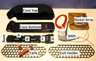
I've found the down tube packs to have the lightest cases and the best bike balance,  I also like the smooth nonconductive plastic with rounded corners so that I don't hurt myself as much.  After I'd installed half a dozen different styles of down tube cases I settled on the Reention DP-6 case as my standard choice.  It will fit 65 cells in a 13 serial by 5 parallel pattern (13s5p), which if  assembled with 3500 mAh cells adds up to 840 Watt hours (48V x 17.5Ah).  This is as good as I've been able to fit in the front triangle of most bikes I've converted.  (Reention does make a DP-9 case but it's usually a bit too big and if more Wh are truly needed, I end up using a 1 kWh (13s6p, 48v x 21Ah) rear rack battery.)  I often have a DP-6 on the shelf because I'm  converting a bike.  Having a standard battery came in handy for the Upper Valley Ebike Lending Library last summer when they dropped a battery.  I was able to substitute one of mine while I glued the broken case back together.  (PVC pipe plumbing glue from the hardware store works well.)  Because of this background, the Stratus got a Reention DP-6, 48 Volt, 17.5 Ah, 840 Wh battery without a second thought.

An empty Reention DP-6 case ready to be stuffed with cells.  When purchasing an already built battery, I look for one with name brand cells and a BMS that has at least a few certifications.  I prefer this case because the base has these features:
A. it has 4 retention tabs down each side instead of 2
B. a full length aluminum spine instead of 1/2 way 
C. 5 large spade terminals that can be doubled up
D. no large cavity for a controller that I don't need  

For comparison most of the Hailong cases available have only 2 retaining tabs per side plus the empty cavity for a controller with a shorter spine, and use bullet terminals that can fill with water and dirt when the bike is transported with the battery removed.

However the DP-6 case could still be improved by adding these 3 features:
1. an IP-65 rating (to match the BBS02) and a more waterproof switch.  These cases are OK in the rain, (I've ridden in downpours without a problem), but they can't take a garden hose pointed directly at the switch and connectors.  In many ways they remind me of the electrical switches on the motorcycles of my childhood, which had bare switch contacts screwed inside a plastic shell on the handlebars that were very exposed to the water coming in.  There were millions of these switches made for decades and they worked, but we can do better now.
2. a Vee channel molded up the center under the base to fit on down tubes more securely.  Numerous companies make water bottle and accessory mounting rails with this groove, and Grintech's Bottle Bobs also have this groove, here's an example:
3. an XT60 socket instead of wires.  Here is an example that I made for a mountain ebike conversion:
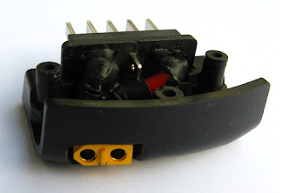
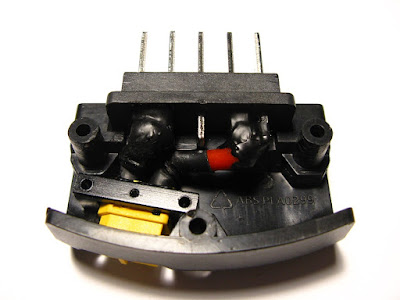
The terminal base of the DP-6 fitted with an XT60 plug.  Normally the power wires would exit here.
The outer 2 spade terminals are paralled together for each pole.  The short wiring is almost stiff enough to hold the XT60 in place by itself, but a RC connector hold down strap was also added.  Note: live power receptacles should have recessed female sockets, similar to household wall receptacles.  Using exposed male terminals that could easily be shorted is not good practice.

BBS02 motors come with a 20" lead, the battery cases have a 12" lead, and usually there is a 10" long adapter cable for a total power cable length of 42 inches.  This is a bit long since the distance from battery to BBS02 is around 9" on most bikes.  I cut a lot of this out and leave only one pair of connectors.  However the Stratus motor is a foot forward of the battery so I kept the wires and hid an XT60 connector under the battery base instead of fitting an XT60 terminal into the base. 

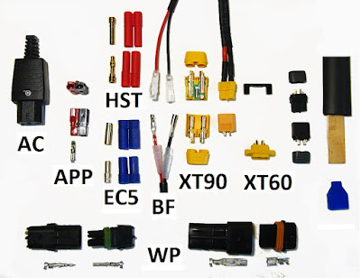
Connectors I have loved or left
(First loves on left, current connections on right)

AC-The first battery connectors I used were AC power cord plugs such as on a computer printer- big and heavy, just like the LiFePO4 batteries they came on.

APP-I used to use Anderson 45 amp Power Pole connectors, but found that the jiggling wires twisted the contacts apart slightly during riding, and then the contacts started sparking and pitting.  This would melt the housing, and then all hope of getting home was lost. (Although hard to see, in this picture the red housings are melted, and the contact is pitted.)  After the second meltdown, I moved on.

EC5  (blue)- I liked these, they're tough and stayed together, but they are completely open to water
HST (red)- a little smaller than the EC5, but the spring contact collar squished I was while playing with them on the bench, so I never put them on a bike.  These are the same size as banana plugs though, so I'd consider using them for a bench testing setup.

BF- These are Bafang bullet terminals, which are not the same diameter as common 1/8" bullet terminals.  I liked these a lot because they have most excellent silicone rubber boots.  But they have a very weak neck between the wire crimp and the socket, and after breaking 3 of them off I now only use them for the connection inside the BBS02 between the controller and the windings.

WP- Delphi Packard Weatherpack automotive connectors (similar to AMP/Tyco/Molex) did not rate a trial, they are either too low in amps for a suitable size (20A on left), or too big for a usable amp rating  (46A on right) due to their stamped steel terminals.

XT90- The early motor controllers I used had large capacitors in the input circuit, and there would be a very bad spark when plugging the battery in.  The XT90S version has a resistor that moderates this spark and was a step up for my earlier bikes.  But they are big and heavy, and my batteries have switches now.  Normally this connector would have a solid yellow exterior casing but I sat down one night with a hacksaw and an Xacto knife and cut a connector in half to see the resistor, shown in the photo.  .

XT60- My current fave.  There are several versions shown in this photo.  Machined brass terminals give a 60A rating in the smallest package, (my rides consistently have 12 to 18 amp climbs, with some momentary spikes to 30A, so this is a good safety margin). Because the standard yellow version on the left has a hooded design it can be reasonably water resistant if you put heatshrink and silicon caulk around the outside wires, and then smear the terminals and inside hood with silicone grease before plugging them together.  I'm using the gray version on the right which has snap on outside covers.  I still put heat shrink tubing over the wire solder joints to provide some bending strain relief for the wires, then I fill the area with silicone caulk and snap the cover on.  After drying it's a pretty robust setup.  I've tried to improve this by putting a boot over the connector, however the available boots (in blue) are too short.  A substitute is a piece of heat shrink that is an inch longer than the connector with some caulk sealing the stationary end.  (I place a wood shim in the tubing while shrinking it so that afterwards when I remove the shim there will be some slack.)   However I think the best protection so far is putting the XT60 inside the battery base.  The black aluminum U shaped RC model hold down strap for the connector is shown near the top.  Note: the yellow bulkhead connector at the bottom with exposed male terminals is OK for an appliance that draws power, but shouldn't be used on a battery that is a power source.

All of the large forces on a battery case act to press the case and the downtube together, and the 2 small bottle mount screws are sufficient for most riding.  On standard diamond frame bikes I prefer to install a third screw for additional sideways strength when the bike is ridden with the frame tilted.  (The Vee groove battery base improvement would help here.)  I use an M5 popnut that matches existing bottle mount hardware.
A popnut gun with M5 inserts.  A bolt with nuts and oiled washers (center) can also be used to compress the popnut with some effort because it will try to unscrew while compressing

An easy way to find the center of the downtube is to clamp a stick on each side, and then put a mark on a piece of masking tape halfway between the sticks.

The Stratus didn't have any bottle mounts on the tube for the battery, and I decided not to drill holes in the frame.  I switched to tee nuts held on by hose clamps instead.

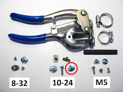
A metal hole punch is used on the hose clamps.  The 3 sizes of tee nuts I use are at the bottom, along with a piece of heat shrink tubing for covering the clamp.  The tee nut in the red circle has been bent to fit the frame tubing.

Furniture Tee nuts come in many styles, I use the type with 3 small holes.  (Metric tee nuts are not available here and I've been using M5 Weld nuts instead.)  The 8-32 size will slip into most battery base mounting slots but it's a bit light duty.  I often use the 10-24 size but the base slots need to be filed slightly wider.  The M5 size requires a lot of filing for use with a battery base, but once in a while this thread size is necessary for mounting an accessory.

I start by tightening the hose clamp on the frame in the desired position and marking the location for the hole in the clamp band for the tee nut with a Sharpie marker.  A metal hole punch works better than trying to drill a hose clamp.  Drilling is possible but start undersize and then use a chainsaw file to smooth out the hole and move it back towards where it was supposed to be.

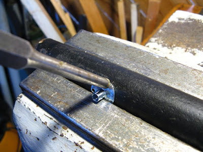
Using a pipe, vise and punch to bend a tee nut to fit the tube.
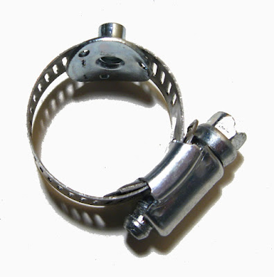
Sometimes the tee nut has to be trimmed, but most often the shim washers and hose clamp take up any excess height.  I bend the tee nut to a radius that matches the frame tube, slip it into the hose clamp, and then fit a piece of heat shrink tubing over the clamp band (with cutouts to fit the tee nut and screw housing) to protect the paint on the bike.
A hose clamp with a tee nut fitted, then I cover this assembly with heat shrink.


The Stratus hose clamp mounts installed.  The power cable to the motor runs under the base.

For the Stratus I tried to hide the screw heads up under the base, but they could be pointed down for easier access.  The heads were useful in this position for holding the wiring and XT60 connector in place.  I also painted the screw housings black to blend in.  Hose clamps and tee nuts provide a very secure mounting, it's just that they aren't as clean looking or light as a pop nut.

I'll write one more short post to finish up this series about The Breeze - the Stratus,  with a couple of the other small details that make it a nice bike.